 2026-06-16
 A precision motor shaft is a machined rotating component that transmits torque from a motor's rotor to an external mechanical load — but the word "precision" carries specific engineering meaning that separates these parts from standard commercial shafts. A precision motor shaft is defined by tightly controlled dimensional tolerances, strict geometric accuracy requirements (roundness, cylindricity, straightness), and surface finish specifications that allow the shaft to operate at high speeds, carry accurate loads, and interface reliably with bearings, couplings, encoders, and driven components over a long service life.
In practical terms, a standard commercial shaft might be manufactured to an h8 or h9 tolerance class with surface roughness in the Ra 1.6–3.2 µm range — adequate for general industrial use but too loose for applications demanding accurate positioning, low vibration, or long bearing life at high rotational speeds. A precision motor shaft, by contrast, is typically manufactured to h5, h6, or tighter tolerance classes with surface roughness between Ra 0.2 and Ra 0.8 µm at bearing journals and coupling seats. At these tolerance levels, dimensional variation is measured in micrometers, and the geometry of the shaft — its straightness, runout, and cylindricity — must be verified with instruments capable of resolving sub-micron deviations.
This level of accuracy matters because even small deviations in a precision motor shaft directly translate into performance problems: a shaft journal that is 10 µm out of round will cause the bearing to experience cyclic loading at rotational frequency, generating vibration and accelerating bearing fatigue. A shaft with 20 µm of runout at the encoder mounting location will produce position feedback errors that degrade the accuracy of a servo control loop. In medical devices, semiconductor equipment, aerospace actuators, and high-speed machining spindles, these deviations are not acceptable — and that is the environment precision motor shafts are designed for.
Material selection for a precision motor shaft is driven by the required combination of strength, machinability, hardness, corrosion resistance, and magnetic properties. No single material excels in all these attributes simultaneously, which is why precision shaft materials are carefully matched to the specific demands of each application.
Medium-carbon steels such as AISI 1045 and alloy steels such as AISI 4140 and 4340 are the workhorses of precision motor shaft manufacturing. They offer an excellent balance of tensile strength (typically 600–1,000 MPa in the normalized or quenched-and-tempered condition), good machinability, and the ability to be surface-hardened by induction hardening or case carburizing to achieve surface hardness values of 55–62 HRC at bearing journals while retaining a tough, ductile core. This combination — hard surface for wear resistance and fatigue strength at stress concentration points, tough core for impact resistance — is ideal for servo motor shafts, stepper motor shafts, and general industrial precision motor output shafts where torque loads are significant and surface durability is critical.
AISI 4140 chromium-molybdenum steel is particularly popular for precision motor shafts because it responds predictably to heat treatment across a wide range of section sizes, machines cleanly to fine surface finishes, and maintains dimensional stability after heat treatment when stress-relief annealing is included in the manufacturing sequence. For very high-strength applications — such as shafts in aerospace servo actuators or high-torque direct-drive motors — AISI 4340 nickel-chromium-molybdenum steel provides tensile strengths above 1,200 MPa with excellent toughness.
Stainless steel precision motor shafts are required wherever the operating environment involves moisture, corrosive chemicals, food contact, or cleanroom conditions that prohibit the use of uncoated carbon steel. AISI 303 and 304 stainless steels are used for lightly loaded shafts where corrosion resistance is the primary driver and mechanical strength requirements are moderate. For higher-strength applications, martensitic grades such as AISI 416 or 440C are heat-treatable to hardness levels above 55 HRC, providing both corrosion resistance and the surface hardness needed for long bearing life. AISI 17-4PH precipitation-hardening stainless steel is used in demanding applications combining high strength (above 1,000 MPa), moderate corrosion resistance, and excellent dimensional stability after age hardening — making it a common choice for precision shafts in aerospace and medical device motors.
In certain motor designs — particularly brushless DC motors with Hall effect sensors, MRI-compatible medical motors, and motors operating near sensitive magnetic field measurement equipment — the shaft must be non-magnetic to avoid disturbing the motor's magnetic circuit or the surrounding environment. Non-magnetic precision motor shafts are commonly made from austenitic stainless steels (304, 316), titanium alloys (Ti-6Al-4V), or beryllium-copper alloys. Titanium shafts additionally offer very high strength-to-weight ratios and excellent fatigue resistance, making them valuable in weight-critical aerospace and robotics applications despite their higher material cost and greater machining difficulty compared to steel.
The dimensional and geometric specifications of a precision motor shaft are not arbitrary — each tolerance requirement exists because a specific aspect of shaft geometry directly affects a measurable performance outcome. Understanding which tolerances matter most for each application zone of the shaft helps engineers specify correctly and avoid over-specifying features that add cost without adding performance.
| Shaft Feature | Typical Precision Tolerance | Performance Impact if Out of Tolerance |
| Bearing journal diameter | IT5 / IT6 (h5, k5, m5) | Incorrect bearing fit, vibration, premature bearing failure |
| Coupling or pulley seat diameter | IT6 / IT7 (h6, k6, j6) | Slippage under torque or fretting corrosion at interface |
| Runout at bearing journals (TIR) | ≤ 2–5 µm | Vibration at rotational frequency, reduced bearing life |
| Runout at encoder mount | ≤ 2–3 µm | Position feedback error, servo control instability |
| Shaft straightness | ≤ 5–10 µm over shaft length | Bow-induced vibration, uneven bearing load distribution |
| Cylindricity at bearing journals | ≤ 2–4 µm | Non-uniform bearing race loading, rolling element fatigue |
| Keyway position (angular) | ±0.1° to ±0.05° | Misaligned key torque transmission, fretting wear |
| Surface roughness at bearing seats | Ra 0.2 – 0.4 µm | Scoring of bearing inner race, fretting corrosion |
The relationship between shaft tolerances and ISO system tolerance grades is worth understanding for anyone specifying or inspecting precision motor shafts. The ISO standard IT grade system grades tolerances from IT01 (tightest) through IT18 (loosest). For precision motor shaft bearing journals, IT5 and IT6 are the standard grades — these correspond to diameter tolerances of approximately 6–11 µm for a 20mm journal diameter and 8–13 µm for a 30mm journal diameter. For ultra-precision applications such as high-speed spindle motors or surgical robot actuators, IT4 or tighter tolerances may be specified, requiring grinding and lapping operations to achieve.
The manufacturing sequence for a high-accuracy motor shaft is carefully designed to minimize the dimensional distortion introduced at each processing step and to ensure that the final machining operations are performed on a stable, stress-free workpiece. Shortcuts in this sequence — such as skipping stress relief after rough machining, or grinding before heat treatment — consistently produce shafts that fail to hold tolerance in service as residual stresses relax during operation.
The manufacturing process begins with turning the bar stock or forging to rough dimensions on a CNC lathe, leaving 0.3–0.5mm of stock on all functional surfaces for subsequent grinding operations. Centre holes are drilled at both ends of the shaft to precise dimensional standards — these centres serve as the datum reference for all subsequent turning, grinding, and inspection operations, so their accuracy is foundational to the accuracy of every subsequent dimension. After rough turning, a stress relief heat treatment cycle (typically 550–650°C for steel alloys, held for 1–2 hours and slow-cooled) removes residual machining stresses that would otherwise distort the shaft when material is removed in subsequent finishing operations.
For shafts requiring surface hardening, the heat treatment stage follows rough machining and stress relief. Induction hardening is the most common method for precision motor shafts — it allows bearing journals and other wear-critical zones to be selectively hardened to 55–62 HRC while leaving transition zones and threaded features at lower hardness to prevent brittleness. The depth of the hardened case (typically 1–3mm for most motor shaft diameters) is controlled by the induction coil geometry, frequency, and dwell time. After hardening, a low-temperature tempering cycle (150–200°C for 2 hours) relieves quench stresses and stabilizes the martensite structure without significantly reducing surface hardness. The shaft is then straightened if necessary — heat treatment invariably introduces some bow — before proceeding to finish grinding.
Cylindrical grinding between centres is the primary finishing operation for precision motor shaft bearing journals, coupling seats, and other critical diameter features. The shaft is mounted on its centre holes and traversed past a rotating abrasive wheel that removes material in controlled increments, achieving the final diameter, roundness, cylindricity, and surface finish in a single setup. Modern CNC cylindrical grinders with in-process gauging can achieve diameter tolerances within ±1–2 µm and roundness within 0.5–1 µm under stable thermal conditions. The wheel specification — grain type, grit size, bond, and structure — is chosen based on the shaft material and the required surface finish: CBN (cubic boron nitride) wheels are commonly used for hardened steel precision shafts because they cut more precisely, wear more slowly, and generate less heat than conventional aluminium oxide wheels.
Precision motor shaft inspection is performed on temperature-controlled metrology equipment, typically in a climate-controlled room maintained at 20°C ±1°C, since thermal expansion of steel is approximately 11.7 µm/m/°C — a temperature variation of just 5°C across a 200mm shaft would produce a dimensional change of 11.7 µm, enough to shift a shaft from within tolerance to out of tolerance at IT5 grade. Diameter measurements are made with air gauging or contact probes on a CMM (coordinate measuring machine). Runout and straightness are measured with a precision V-block setup or in a precision lathe using a dial indicator or electronic probe with sub-micron resolution. Surface roughness is measured with a contact profilometer. All measurement results are documented in a first article inspection report (FAIR) that becomes part of the shaft's quality record.
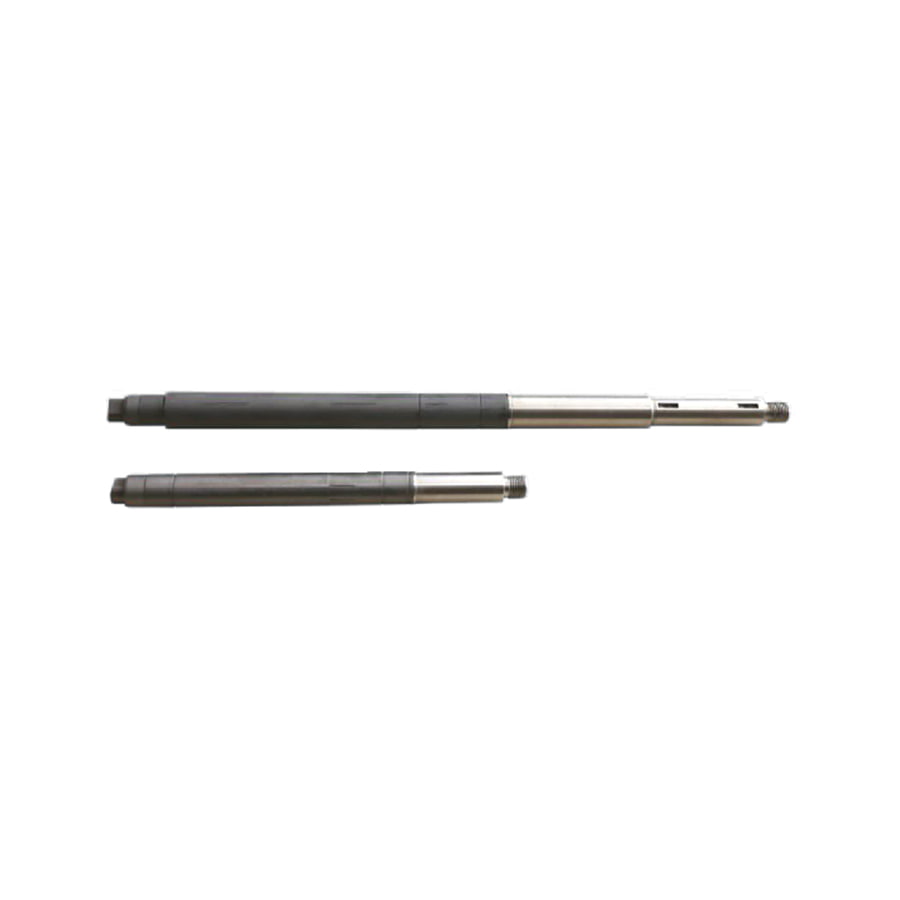
Beyond basic dimensional accuracy, precision motor shafts incorporate specific design features that enable reliable torque transmission, secure component mounting, and easy assembly and disassembly. Each feature must be carefully designed and precisely executed to perform its intended function without introducing stress concentrations or assembly difficulties.
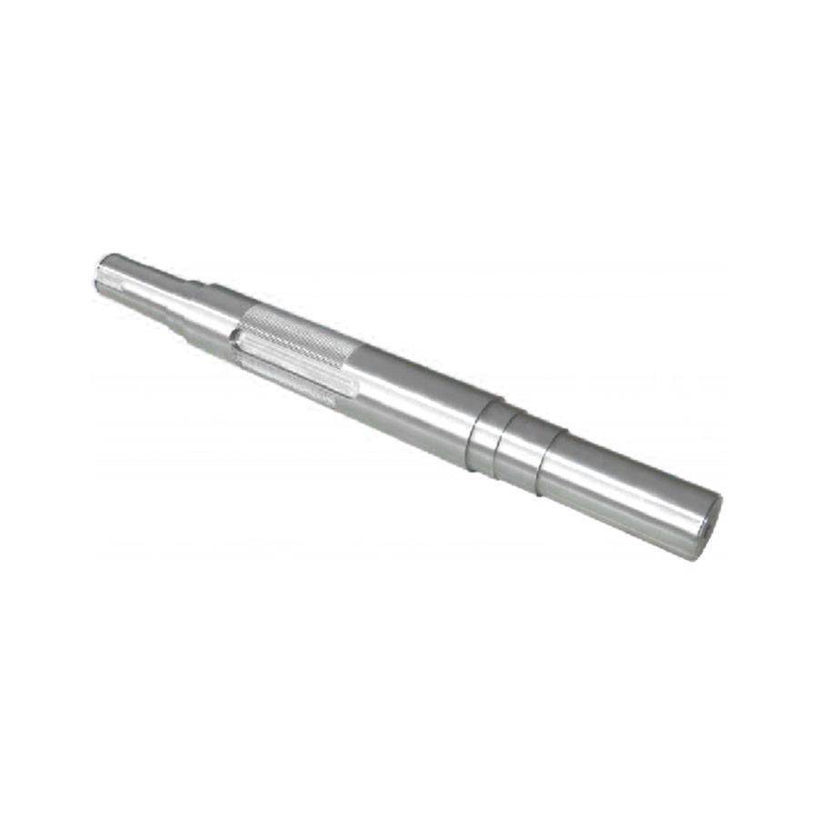
Keyways are the most common torque transmission feature on precision motor output shafts. A parallel key seated in matching keyways in both the shaft and the hub of a coupling or pulley transmits torque through shear across the key cross-section. For precision applications, keyway dimensions are held to tight tolerances — typically JS9 or N9 on the width — to minimize backlash and prevent fretting wear at the key-keyway interface. The keyway should be positioned to avoid the weakest cross-section of the shaft, and the keyway corner radii must be generous enough to reduce the stress concentration factor, which is a common fatigue crack initiation site on motor shafts.
Involute splines are used where higher torque capacity, self-centering, or axial sliding capability is required. Splined precision motor shafts are common in servo motor applications where the driven component must slide axially during assembly or operation. The involute spline profile allows self-centering under load, reducing bending moments at the shaft-hub interface compared to a parallel key connection.
The end of a precision motor shaft typically incorporates features for axial retention of mounted components. A threaded end with a nut and washer, a shaft groove for a circlip, or a tapped hole for a retaining bolt are all common solutions. Threads on precision motor shafts must be cleanly cut and the thread form accurate enough to allow a nut to be tightened without binding, and the thread should be located as far as possible from bearing journals to minimize stress concentration interaction. Flats machined onto the shaft end are sometimes provided to allow the shaft to be held stationary during coupling or pulley installation without damaging the precision bearing surfaces.
Diameter changes along a precision motor shaft — from the bearing journal to the rotor mounting diameter or to the output shaft end — are designed as shoulders with controlled fillet radii at the transition. The fillet radius is a critical fatigue design parameter: a sharp corner at a diameter change creates a high stress concentration factor (Kt) that dramatically reduces the shaft's fatigue limit. For rotating bending applications (which is the dominant loading mode for most motor shafts), increasing the fillet radius from 0.5mm to 2.0mm at a given shoulder can improve fatigue life by a factor of 3–5. Precision motor shaft drawings specify minimum fillet radii at all shoulder transitions and often require that these radii be produced by grinding rather than turning, to ensure they are smooth and free of machining marks that could initiate fatigue cracks.
Understanding how and why precision motor shafts fail allows engineers to design more robust shafts, maintenance teams to identify early warning signs, and procurement teams to evaluate shaft quality more critically. The following failure modes account for the vast majority of precision motor shaft service failures.
Specifying a precision motor shaft — whether for a new motor design, a motor rebuild, or a custom shaft for a special application — requires working through a structured set of engineering decisions. Taking shortcuts in this process consistently leads to either over-specified (expensive) or under-specified (unreliable) shafts.
 CategoriaSuadeo Post

Fenglan est Electrical Precision Parts Manufacturer in China, Automotive Precision Parts Proin et Industrial Precision Parts Suppliers. Your Reliable Socius in Partibus et Componentibus Vestibulum cum 2010
 Tel: +86-13861233850
  E-mail: [email protected]
  Add: No.60, Orientem Zhuanghe viam, Chunjiang oppidum, Wei Villa, Xinbei dolor, Changzhou urbem, Sinis
  Secretum


 +86-13861233850
 2025-09-17