 2026-07-16
 Precision electrical connector terminals are the small metal components inside a connector that create the actual electrical contact point between a wire and a mating connector, circuit board, or component. While connector housings get most of the visual attention, the terminal itself is what determines whether a connection carries current reliably over years of use, vibration, and temperature cycling. These terminals are manufactured to tight dimensional tolerances because even minor variations in contact geometry can affect insertion force, contact resistance, and long-term connection stability.
The word "precision" in this context isn't just marketing language. It refers to the manufacturing tolerances held during stamping, forming, and plating, which directly influence how consistently a terminal performs across thousands or even millions of mating cycles. In industries like automotive electronics, aerospace, and medical devices, a terminal that's out of spec by even a few microns can lead to intermittent connections or complete circuit failures, which is why terminal quality control receives so much attention during manufacturing.
Terminal design varies significantly depending on the application, wire gauge, and mating connector style involved. Knowing the main categories helps when specifying replacement parts or designing a new wiring harness.
Most precision terminals are stamped from copper alloys such as phosphor bronze or brass, chosen for their combination of electrical conductivity and spring properties needed to maintain consistent contact pressure over time. Beryllium copper is sometimes used in higher-performance applications because of its superior fatigue resistance, though cost and handling considerations limit its use to more demanding designs.
Terminal plating protects the base metal from corrosion while also affecting contact resistance and mating durability. Gold plating offers excellent corrosion resistance and low contact resistance, making it a common choice for low-voltage signal connections where reliability is critical. Tin plating is more cost-effective and works well for higher-current power connections, though it's more prone to fretting corrosion in applications with frequent micro-vibration.
Choosing the right plating comes down to balancing performance requirements against budget constraints. The table below summarizes how common plating choices stack up.
| Plating Type | Contact Resistance | Corrosion Resistance | Typical Application |
| Gold | Very Low | Excellent | Low-voltage signal and data connections |
| Tin | Moderate | Good | General power and automotive wiring |
| Silver | Low | Moderate, tarnishes over time | High-current applications needing low resistance |
| Nickel Underplate | Depends on top layer | Very Good | Used as a barrier layer under gold or tin |
Every terminal is designed for a specific wire gauge range, and using a terminal outside that range compromises the crimp quality. A terminal too large for the wire won't compress the strands adequately, while one too small can damage the wire strands during crimping, both of which lead to weak, unreliable connections.
Terminals carrying higher current need sufficient contact surface area and spring force to prevent excessive heat buildup at the connection point. Applications operating in high-temperature environments, such as engine compartments, also require terminals and platings rated to withstand sustained thermal exposure without degrading.
Connectors that will be mated and unmated frequently, such as test equipment or field-serviceable connections, need terminals rated for a higher number of mating cycles. Terminals designed for permanent or rarely disconnected applications can often use simpler, lower-cost designs since durability under repeated insertion isn't a major concern.
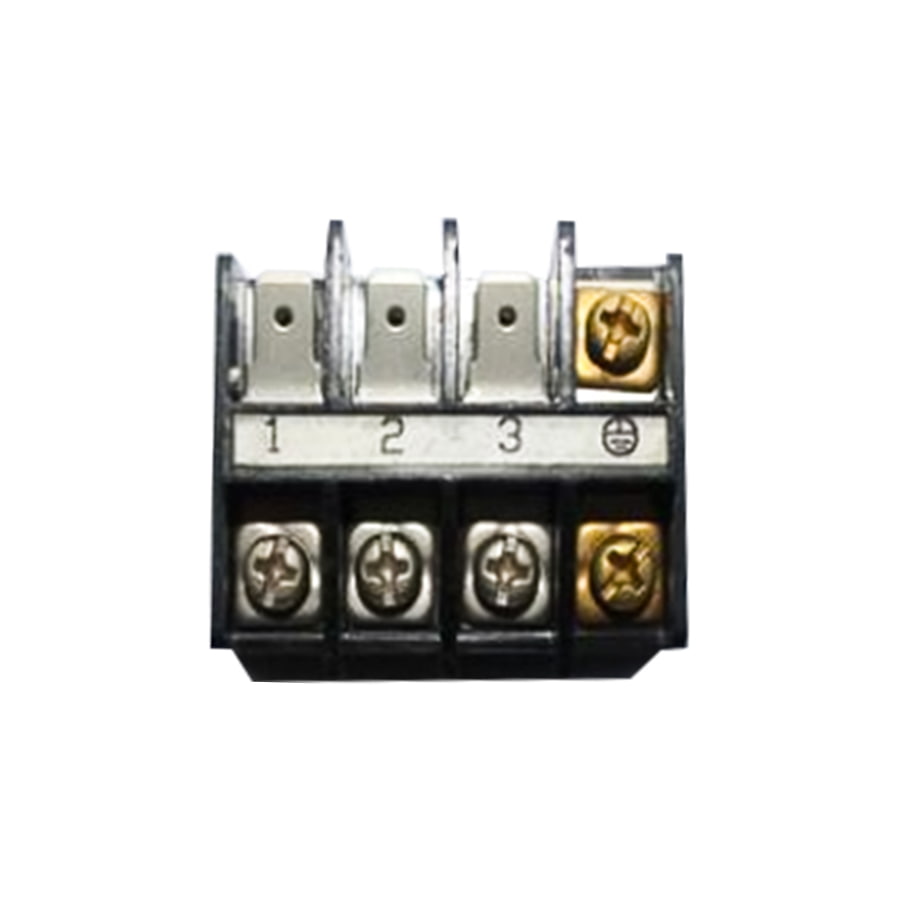
Even the best precision terminal will fail prematurely if it's crimped incorrectly. Using the correct crimping tool and die set matched to the specific terminal manufacturer's specifications is essential, since generic or mismatched tooling often produces inconsistent crimp height and width, leading to weak mechanical retention or increased contact resistance.
Stripping the wire to the correct length before crimping also matters more than it might seem. Too much exposed conductor can create a short circuit risk, while too little strand length prevents the terminal from making full contact with the conductor. Many manufacturers recommend performing periodic pull tests on sample crimps during production to confirm the connection meets minimum retention force specifications.
For applications involving vibration or repeated thermal cycling, adding strain relief near the terminal connection point helps prevent fatigue at the crimp interface over time. This is particularly important in automotive and industrial settings where wiring harnesses are subject to constant movement and temperature swings throughout their service life.
Precision electrical connector terminals might be small, often-overlooked components, but they play an outsized role in the overall reliability of any electrical or electronic system. Choosing the right terminal type, material, and plating for the application, combined with proper crimping technique and installation practices, makes the difference between a connection that lasts for years and one that causes intermittent failures down the road. Taking the time to get these details right during design and assembly pays off through fewer field failures and a more dependable end product.
 CategoriaSuadeo Post

Fenglan est Electrical Precision Parts Manufacturer in China, Automotive Precision Parts Proin et Industrial Precision Parts Suppliers. Your Reliable Socius in Partibus et Componentibus Vestibulum cum 2010
 Tel: +86-13861233850
  E-mail: [email protected]
  Add: No.60, Orientem Zhuanghe viam, Chunjiang oppidum, Wei Villa, Xinbei dolor, Changzhou urbem, Sinis
  Secretum


 +86-13861233850
 2025-09-17